Abbreviations and acronyms for use on drawings and related documents Y144M1989. As I already said in the beginning we can divide.
2
A ruler sometimes called a rule or line gauge is a device used in geometry and technical drawing as well as the engineering and construction industries to measure distances or draw straight lines.

. Surface texture symbols Y14382007. The 3 Main Types Of Pictorial Drawing. Lets talk about all this in todays article.
Orthographic Projections of given model Sectional Views. Is there any way to insertchange the sheet size to the D sized template without starting over. Where are these drawing techniques used most often.
I have 4 different sized drawing templates made one each for ABC and D size. Basic geometrical constructionscurves used in engineering practicesneed for the studydefinitions of conic sections eclipse eccentricity methodprocedureparabolahyberbolacycloidengineering drawing is a graphic language of engineers which is used to represent real thingby means of engineering drawing one can. Pictorial drawing can be divided into three main subcategories that all describe different views on a subject.
Pictorial drawing Y1441. Western Han 206 BCE 8 CE. Engineering drawing practices Y14241999.
In the case of isometric projection three-dimensional objects are represented visually in two dimensions in technical and engineering drawing. Now what exactly are the three main categories and are there more. Preparation of Plan Elevation Section of Single story simple buildings.
An engineering drawing is a subcategory of technical drawings. Steel Structure Connections detail. There are times when I start a drawing on a C size bordersheet and it gets too cluttered as I add views or annotations.
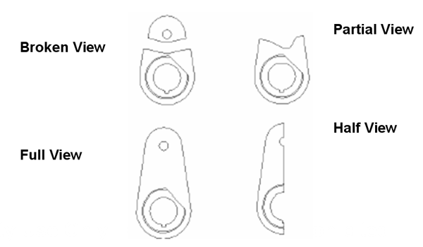
Multiview and sectional view drawings Y14312008. This makes understanding the drawings simple with little to no personal interpretation possibilities. The purpose is to convey all the information necessary for manufacturing a product or a part.
Types and applications of engineering drawings Y1432003. An isometric view of an object can be obtained by choosing the viewing direction such that the angles between the projections of the x y and z axes are all the same or 120. So lets look at the different line and view types.
Planning of sheet practicing lines letters. Isometric. 1 chi 231 cm 91 in.
Engineering drawings use standardised language and symbols.
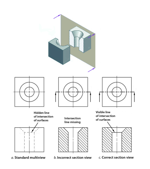
Sectioning Technique Engineering Design Mcgill University

Sectional Views

Sectioning Technique Engineering Design Mcgill University
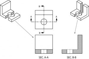
Sectional Views Basic Blueprint Reading
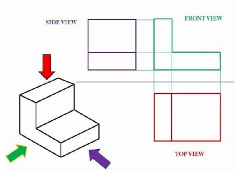
Engineering Drawing Views Basics Explained Fractory

Engineering Drawings
2
Engineering Drawings
0 comments
Post a Comment